Introduction
In this section I explain all necessary steps to obtain a mathematical camera model.
Pinhole Camera – Image formation
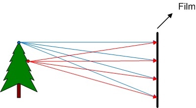
If we put a film directly in front of the object that we want to shoot (figure 1), we realise that we can not take a photo in that way.
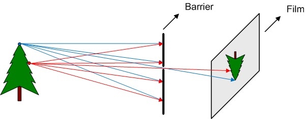
To use the pinhole camera produces perspective effects:
- Far objects appear smaller
- Distances and angles are not preserved
There is an optimum aperture for pinhole cameras (figure 3).
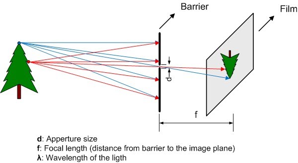
If aperture is too large we don’t block enough light rays and the image is blurred, if aperture is too small the image can be blurred as well due to wave properties of the light (Wiki pinhole camera).
Ideally the depth of field in a pinhole camera is infinite, this mean that the image blur does not depend on the object distance. But there are other factors that can blur the image, such as aperture size, focal length, and wavelength.
Pinhole Camera – Perspective projection equations
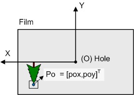
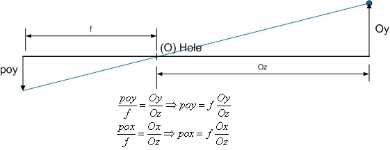
In the figure 4 we can see how to project a 3D point (PO) from the real world into a film. In an easy way we can calculate the film point (Po) where the PO is projected, we only have to know the focal length (f) and obviously the object position point PO.
We have to note that all coordinates are hole (O point) referenced (O = [0,0,0]).

Lens camera – Image formation
To calculate this kind of lens you can see this paper of Virginia University. Aassuming paraxial approximation (incidence angle of light rays << 1 in radians) this lens forces that all parallel rays converge to one point f (focal point), that can be related with the hole in pinhole camera.
Other assumptions are taken:
- Approximate aspheric lens by spheric lens
- Thickness of lens t << R1, R2 (R1, R2 = Radius of lens surfaces)
- d << R1, R2
- The lens are purely refractive, NO reflection and NO diffraction are taken into account
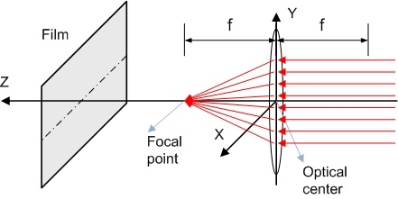
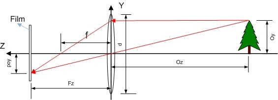
If the object is far enough from the lens (more than f) we can calculate the object projection onto film using following properties (figure 6):
The light rays parallel to the optical axis of the lens are deviated and they crosses in f (focus point), and if a light ray that cross the f (focus point) incide into the lens go out parallel to the optical axis.
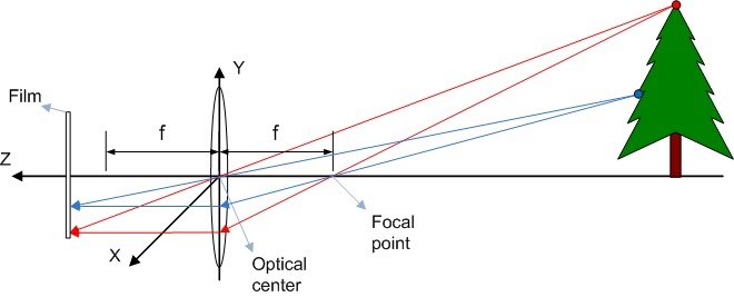
In order to facilitate the calculus understanding we can simplify the model calculating the projection size for 1 dimension, and after that extrapolate the results to 2 dimensions. Work with smaller objects simplify the mathematical approach as well, see figure 7.
Applying similar triangles you can easily derive the following equation obtaining the projection height (poy) and the thin lens focus equation, figure 8.
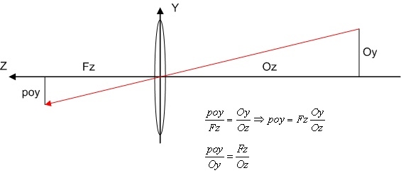
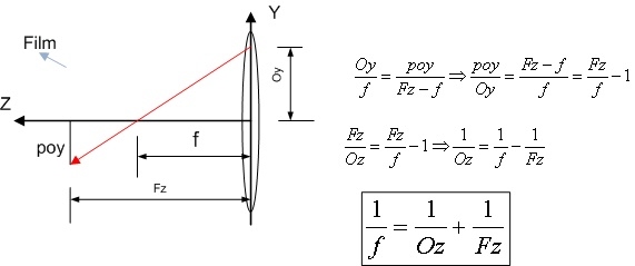
This means that all object point that satisfy the equation 1/f = 1/Oz +1/Fz will be in focus. For example if we put the film in f point only objects in the infinite (Oz >>> d) will be focused, see figure 9.
To summarize the camera model, the results obtained to convert 3D point into 2D coordinate (if we put the film in Fz = f):
- poy = (f/Oz)*Oy
- pox = (f/Oz)*Ox
Lens camera – Field of view (FOV)
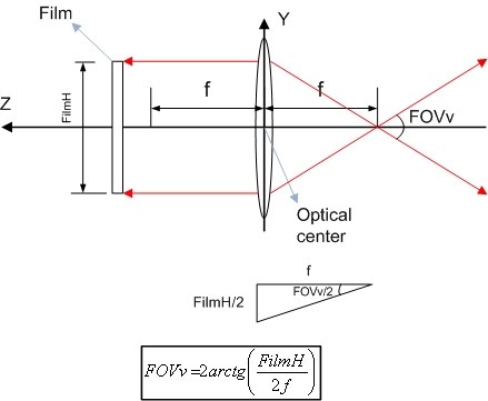
The field of view (FOV) is defined as the angle that the camera can “see”, it can be horizontal FOV (x axis), vertical FOV (y axis) or diagonal FOV (see figure 9).
FOV depends of 2 factors:
- Size of image sensor
- Greater sensor -> More FOV
- f
- Higher f (Zoom effect) -> Less FOV
Lens camera – Depth of filed (DOF)
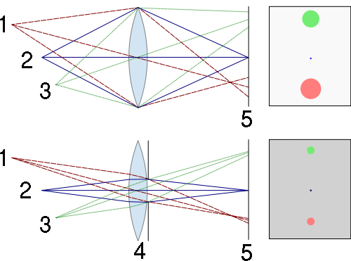
Another interesting concept is the depth of field (DOF), that is the Z range where real objects appears clear in the image (not blurred). Ideally if we apply the previous equation and we put the image sensor in Fz=36mm and the lens has f = 35mm, then the Z object position where appears in focus is Oz = 1260mm, but this is not absolutely true, exists a certain range close to Oz where the objects appears clear defined as DOF.
The DOF depends of 3 factors:
- Apperture (or iris)
- More aperture -> More light -> Less DOF (see Figure 10)
- f
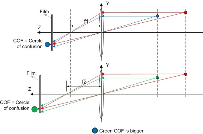
- Higher f -> Bigger circle of confusion (COF) -> Less DOF (see Figure 11: f2 > f1)
- And indirectly: Image sensor size
- Bigger sensor (same FOV) -> Higher f -> Less DOF (see this article)
